


We use cookies on our website to provide you with the best user experience. If you're happy with this please continue to use the site as normal.
For more information please see our Cookie Policy.
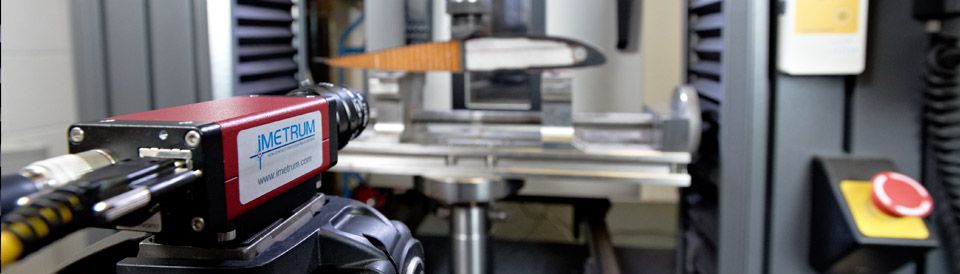
When investigating the behaviour of components and assemblies, the multi-point abilities of our systems has repeatedly helped engineers investigate the true behaviour of their components. They are able to measure the following properties, each to a sub-pixel accuracy:
- Position
- Displacement
- Rotation
- Bend Angle
- Strain
Using these details, each element can be studied with a new level of detail, as outlined in examples below. Setups can include up to four cameras, allowing for additional cameras to look at multiple faces or to focus on small areas for higher resolution measurements. View our Mobius product page.
Track Rod Displacement
When crosshead displacement measurements were giving unsatisfactory results, our system was bought in to take over. The 600mm track rod length was straining more than expected, and so it was necessary to find out where the slack in the system was coming from.
Using our system we were able to monitor the different metals and composite elements, along with the strain across the joints and bearing involved. The crossheads and fixtures were also monitored to determine the degree of alignment and compliance within the test frame. Using this approach, the straining of each section could be analysed, and it was found that the previously recorded crosshead displacements were a result of the test frame compliance, and the track rods were performing as predicted by the FEA
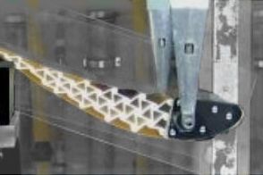
Wind-Tunnel Wing Deflection
Our system was utilised to measure the behaviour of the nose and wing sections of a F1 car during wind tunnel testing. The complex array of LVDTs and accompanying wiring that was previously used could be replaced by a single camera system, whilst also removing the disturbance to the air flow.
The detailed data allowed for comparisons against the FEA predictions. These highlighted unexpected differences that were later found to be due to variations from the plan during the lay-up process of the composites. Without this analysis around the complex geometry, these issues would have gone undetected, possibly leading to component failure on track.
High-Speed Impact Testing
Using the post-process mode, video files from other sources can be analysed with our Video Gauge™ software. This has included the feed from a high speed camera running at 5kHz which was used to film the crash test required for an F1 cockpit.
An array of points along the cockpit was monitored, without any fear of damage to system should the cockpit shatter. Sub-millimetre measurements were achieved along the metre length being studied, which allowed the design team to improve their understanding of the component deformations.
For help with any experiments, our experienced engineers are available to help with a free demonstration or advice, so please contact us with any challenges or enquiries.
Videos
Introducing Mobius